


i updated roll bar with new generation feature
 05-12-2018, 05:07 PM
#1

Thread Starter

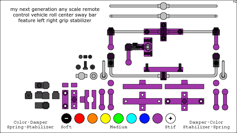
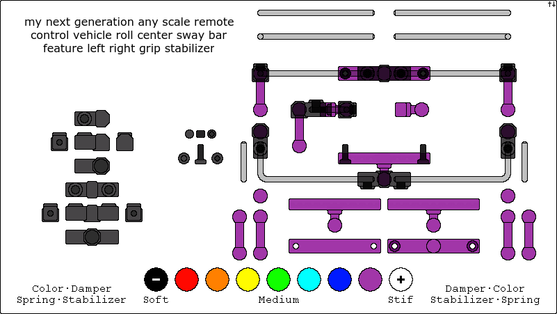
2nd version generation 4
if you raize one side of lower suspension arm it of course lift the other side
but at the same time and or any time and or before that
the ball put preasure on the oposite tire increase grip to drive better at any time left right front rear
1st version generation 3 i dezign that took to much room to many part az double bearing
here iz the original generation - prototype i made a few yearz ago
i would say say
generation 0 iz no sway bar
generation 1 iz a team associated tc5 sway bar no bearing
generation 2 iz a team xray t4 2018 sway bar with bearing
generation - prototype see my prototype
generation 3 prototype see my prototype
generation 4 my center ball thought created 2018 may 13 sunday 02:00 p.m
generation 5 feature my rear generation 4 and or front end connect to front knuckle steering arm and turn when knuckle turn
to compress inside front suspension and decompress out side front suspension that angle main lower chassis plate for
center gravity toward turn instead of the oposite way natural with a example 1:10 scale electric buggy that main lower
chassis plate tip to out side side of car if you turn left chassis top right which iz roll center anti
i make a lot of new generation part see link below
Last edited by 4theoryj; 05-13-2018 at 03:31 PM.
 05-13-2018, 03:44 PM
#2
Thread Starter
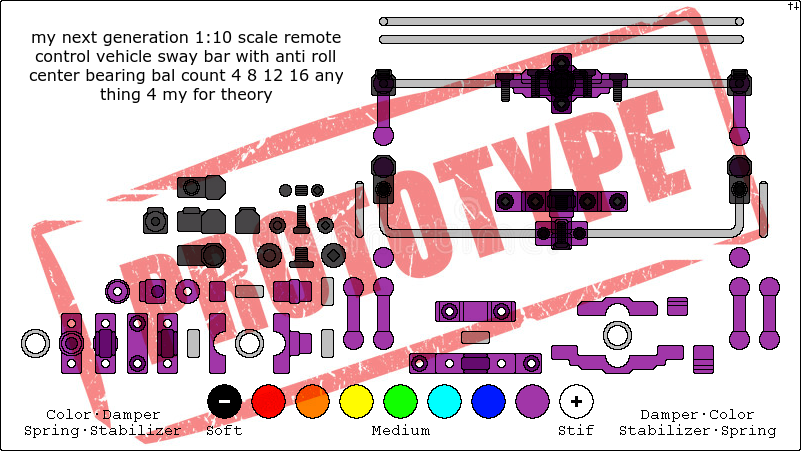
when i dezign the double bearing i hated it for it did not make room the same amount of space mass that this below made

after hard work sufering and a few dayz later today my mind natural told me it like a ball when i woke up that moment with in that next 5 minutez
and to my suprize that i want it to fit like above it doez
after hard work sufering and a few dayz later today my mind natural told me it like a ball when i woke up that moment with in that next 5 minutez
and to my suprize that i want it to fit like above it doez
Last edited by 4theoryj; 05-13-2018 at 11:10 PM.
05-13-2018, 09:10 PM
#3
Thread Starter
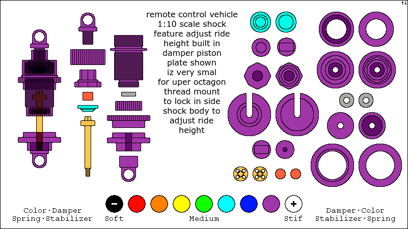
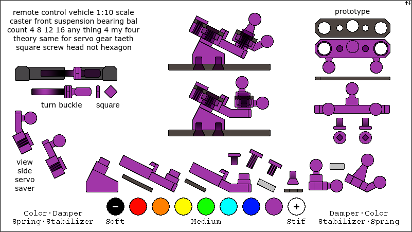
i have just finish making a prototype new generation shock with adjust ride height that doeznot effect spring compression
when you adjust ride height from lower suspension arm you turn a set screw that compress the suspension
this dezign iz on the very top of the shock assembly and you can uze your octagon wrench to adjust ride height
when you adjust ride height from lower suspension arm you turn a set screw that compress the suspension
this dezign iz on the very top of the shock assembly and you can uze your octagon wrench to adjust ride height
Last edited by 4theoryj; 05-14-2018 at 02:43 PM.
 05-14-2018, 12:01 PM
#7
Thread Starter
yup
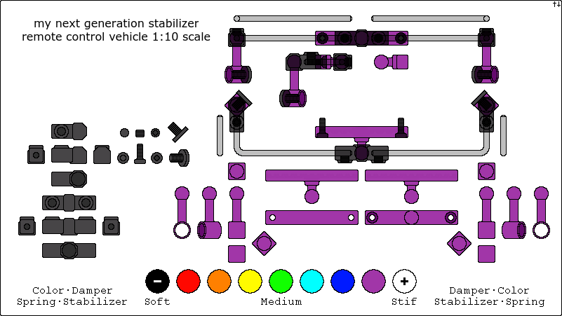
i went thru every part of the 1:10 scale to up grade in to some thing new for the world market
i think i will call the roll center bar generation 2 with prototypez deleted
i went thru every part of the 1:10 scale to up grade in to some thing new for the world market
i think i will call the roll center bar generation 2 with prototypez deleted
 05-14-2018, 05:46 PM
#11
Thread Starter
i re contrust the prototype file
i liked it
any way
you can make a ball for this where the bar iz like the first image of a ball roll center bar
but have it only rotate from roll center
and uze bearing to rotate left right
so it a hybrid
i liked it
any way
you can make a ball for this where the bar iz like the first image of a ball roll center bar
but have it only rotate from roll center
and uze bearing to rotate left right
so it a hybrid
Last edited by 4theoryj; 05-14-2018 at 07:49 PM.
05-14-2018, 10:39 PM
#12
Thread Starter
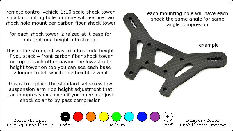
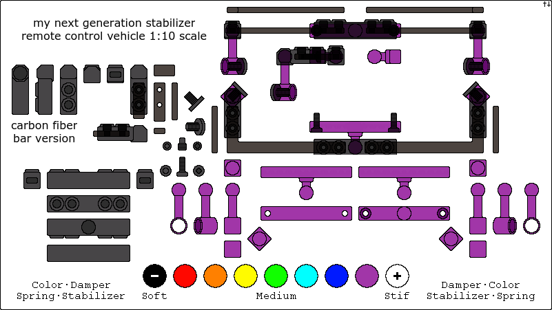
i made a new version to day
it iz the simplist and or cheapest i could make from the double bearing and or ball
well i made a carbon fiber verison the carbon fiber iz to be cut at angle but show image u shape
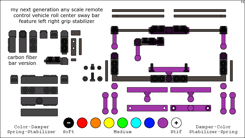
it iz the simplist and or cheapest i could make from the double bearing and or ball
well i made a carbon fiber verison the carbon fiber iz to be cut at angle but show image u shape
Last edited by 4theoryj; 05-15-2018 at 10:17 AM.
 05-15-2018, 11:48 AM
#14
Thread Starter
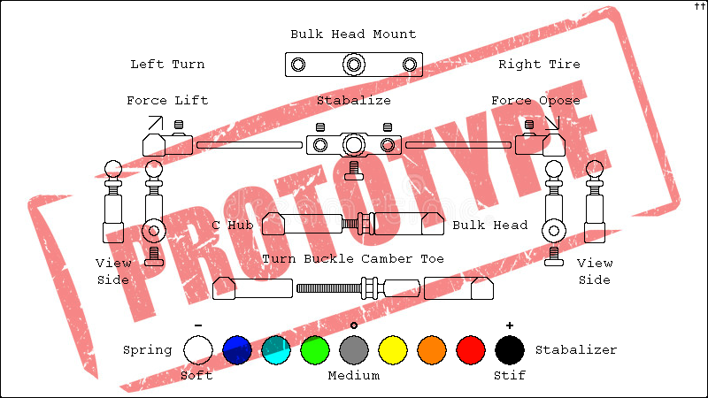
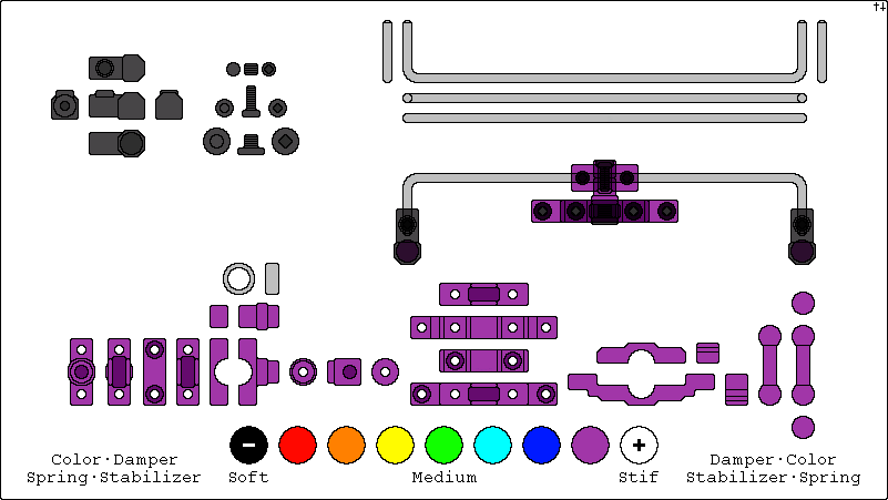
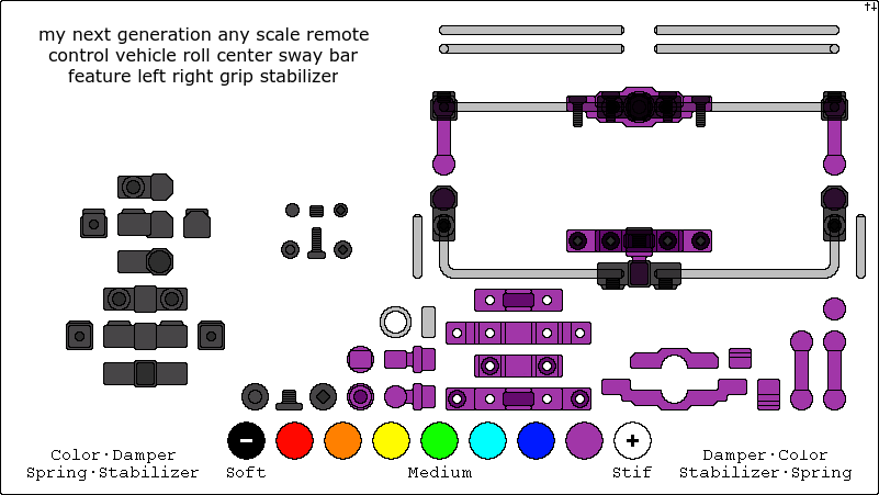
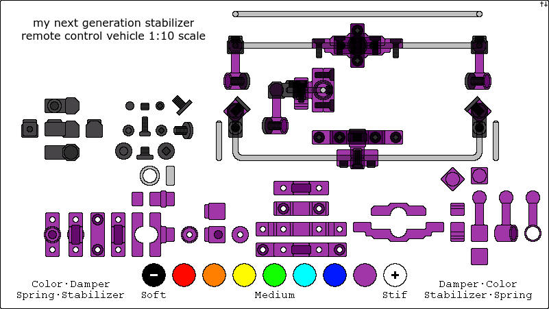
i have one prototype to look at
it uzez a lower shaft mount not a ball mount low arm suspension mount
so it not a double ball mount the bottom iz a hole for a shaft and screw like the bearing mount above
but it mounted at a right angle for the first prototype
becauze if it angle iz straight it bindz when the suspension compress
i am thinking that i cant under stand until i draw it or think about it
that that angle iz important that it linez up left right grip with up down roll
with one of the above versionz to make it rotate
mmmm
like a trick to figure out
05-15-2018, 01:00 PM
#15
Thread Starter
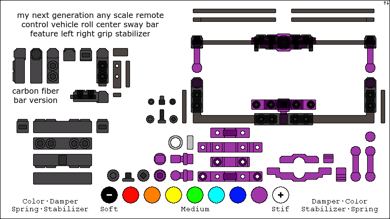
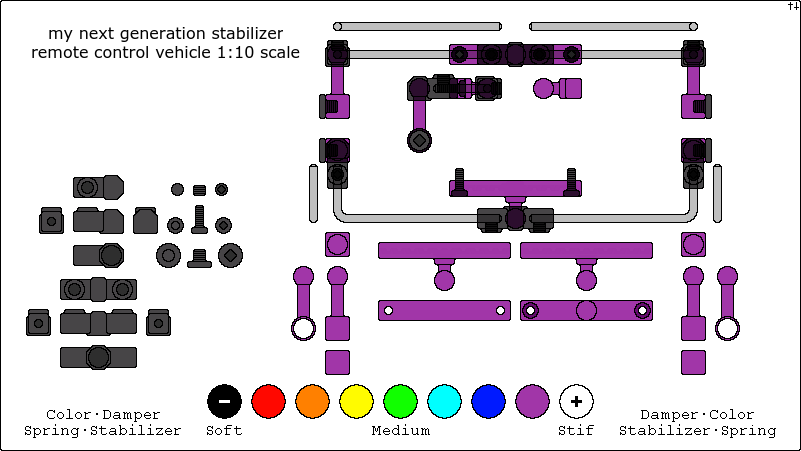
here it iz !!!!
my final prototype
....
and i think it iz my best version out of all of them for price part count eaze of assembly it cheap and the geometery of the angle lower bal
lower suspension arm shaft take the center ball cup that can az a car siting angle left right horizontal and it removez that ability that mean
when you drive it it iz at a angle the bar but with this angle mount the cylinder it can not angle akward
i have chozen theze 3 for my finalz i could add the ball but it for now are theze prototypes
edit i forgot to mention there could be a precise angle not just a 45 degree to this
Last edited by 4theoryj; 05-16-2018 at 02:41 AM.
05-15-2018, 03:42 PM
#16


It’s all BS until it ends up on a model and proven to be a worthwhile “upgrade”. Until theres proof it works and works
better than what’s currently available,’nobody is going to take a second look. Prove this is more
than a bunch of fancy MS Paint drawings.
better than what’s currently available,’nobody is going to take a second look. Prove this is more
than a bunch of fancy MS Paint drawings.
05-15-2018, 03:54 PM
#17
Thread Starter
there are so many people pissed below me....
the next generation
05-15-2018, 06:14 PM
#18
I’m not pissed. I don’t give a crap. What I do give a crap about are innovations that truly make my RC experience significantly better. Example: RPM suspension arms. Better than stock and lifetime warranty. Make a better than stock part that is more durable and better performance for a good price and I will buy it. Throw a bunch of reinvented wheel pictures without any proof the “theory” is better than anything currently available and you will get laughed off like a red headed step child. Post this stuff on a racing forum and you’ll get banned for spamming.
Prove your stuff works in reality and you’ll get better reception.
Prove your stuff works in reality and you’ll get better reception.
05-15-2018, 06:33 PM
#19
Thread Starter
I�m not pissed. I don�t give a crap. What I do give a crap about are innovations that truly make my RC experience significantly better. Example: RPM suspension arms. Better than stock and lifetime warranty. Make a better than stock part that is more durable and better performance for a good price and I will buy it. Throw a bunch of reinvented wheel pictures without any proof the �theory� is better than anything currently available and you will get laughed off like a red headed step child. Post this stuff on a racing forum and you�ll get banned for spamming.
Prove your stuff works in reality and you�ll get better reception.
Prove your stuff works in reality and you�ll get better reception.
ammo.... (repeat mesage]
the theory part iz when you move your stabilizer and it say i cant do that grip so i think in theory az the source that cant find the source so it theory....

Last edited by 4theoryj; 05-15-2018 at 06:37 PM.

 05-15-2018, 07:28 PM
#22
Thread Starter
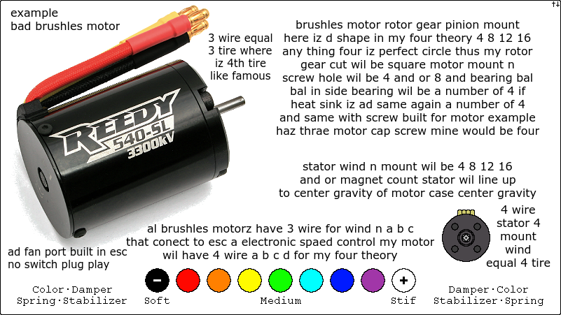
you mean
4 tires
go in the vent....
it even court cases....
i think los angeles try to hide there pride missing
i sent this image with a text to l.a.p.d called bad stuf
emergency over ride....
i uze https://pixlr.com/editor/
4 tires
go in the vent....
it even court cases....
i think los angeles try to hide there pride missing
i sent this image with a text to l.a.p.d called bad stuf
emergency over ride....
i uze https://pixlr.com/editor/
Last edited by 4theoryj; 05-15-2018 at 07:39 PM.
05-16-2018, 01:55 AM
#23
Thread Starter
the only other version i have to all 3 that i have chozen to be my only 3
iz the right angle lower suspension arm shaft
iz instead at a straight angle with the screw on the out side facing the same way the tire faces
then....
if you do a right angle you can also angle that right angle up ward to have two anglez az 1 for the shaft lower mount i am guesing that iz the one you need but you can realy draw it you ahve to cad
i have to look at both
but it coming in close for the final race who will win
Last edited by 4theoryj; 05-16-2018 at 02:50 AM.
05-16-2018, 02:57 AM
#24
Thread Starter
there are two downfals to my designz
all of them
there iz camber change
when you set your turn buckle you have to have in the side turnbuckle mount higher than the outside knuckle mount
when you compress suspension the pre set camber angle extends outward
becauze the angle turnbuckle getz longer az you compress suspension
becuaze it iz a angle iz shorter than a straight line
but after time the camber and width start to degrade
together
and there iz no way you can change this from happening
you can only make it worse by have a turn buckle that iz lower on the inside or turnbuckle that iz straight horizontal
only a mini-z ma-010 with it up down suspension can have camber with zero change in width and or camber
so that iz a rule of thumb
when you do stabilizerz that your lower suspension mount
will never get in the same line az your stabilizer anglez
and it i will degrade after time that it bindz it getz tight
cauze you cant alingn it like camber
this iz the nature of a car
the only downfal
i do not have a computer with 3d cad moveable rendering
to draw a circle of the left right bearing
then a circle of each type of lower suspension mount
and i am guessing if i did all of that
you will still alwayz find a percentage when it compress
that iz bindz you can only reduce it to itz lowest value binding meanz it wantz to pul in another direction and or getz stif to bend in it self the bar will bend in the middle
but never zero
then imagine making this for a ma-010 when i know that you will alwayz seem stuck on a 1:10 suspension
that when you look at ma-010 you feel the same
az it takez up your time the binding the camber change the toe change in suspension compres
you also have kick up to add to that stabilzer i made
where you angle the inner lower suspension hinge pinz upward toward inside the car or the other angle
then you can also angle thoze from a down view to the car out ward and or inward
that go with the angle lower shaft suspension stabilizer mount to make it angle back az
when you compress the roll will angle the the barz back a way from the mount it on
...........................
you also have a ability
to make a shaft that slide in a another shaft ya a shft that slide in a hollow shaft
that can roll with the motion of the suspension and with bal mount angle
but it slide in to the other shaft to roll another direction liek back az a roll center bar doez
to compensate but still achieve both typez of stabilizer
a roll center
and a oposite tire grip
i never tried it
Last edited by 4theoryj; 05-16-2018 at 03:53 AM.
05-16-2018, 04:04 AM
#25
Thread Starter
i had another verson
wheren you have the dobubel ball mount
and there iz no ball cup snap to put on the end of the bar
and you put like a turnbuckle you can find here and there
the metal ball with teh hole in it
ya.....
a left right grip bar
take two double ball suspension mountz ball shaft ball that i have
put a turnuckle ball in side the top of them
slide you bar in with the double bearing mount
if you lift left it compres right
but if you lift both it doez not do any thing
to put a screw
you put that metal ball in to the double ball mount for suspension
when you turn left it compress right
and start to angle the bar you you slide in to the little ball in side that movez liek a turnbuckle ball
then it naturaly liftz up both side
and the sway bar slidez in and out that ball
but there iz friction that comez with it to slide a bar in side a hole that anglez to a force it need to angle
Last edited by 4theoryj; 05-16-2018 at 04:12 AM.