


Composite ARF Mig29
 01-01-2019, 02:16 AM
#526
 01-03-2019, 09:43 PM
#528

While I await some tank hardware to try and upgrade them in place, decided to start looking over the gear. There is nothing quite as disheartening as spending most of an evening disassembling and reassembling the same component over and over to only come away with zero problems solved. :lol:
I sent off an email to Matrix as well, but did anyone here use that gear? Most of the builds I’ve kept up with were the hydraulic system only. Not sure if these issues are common to all gear or just the Matrix.
For starters, way too much toe-in on the mains. Is as though the struts are designed to be mounted perpendicular to the ground, because at 90 degrees the toe looks fine. But adjust the struts forward for the scale angle and the rotation process begins, giving them significant toe-in.
Of course once the toe is set then begins the battle of getting the wheels (5.5” Dubro, not sure how these compare in width to other wheels used) in the wells clean with enough room to close the doors. The mains in this airframe are already mounted on a bed of epoxy, I’m worried I’ll have to grind that out down to the wood to start fresh.
Next, on the nosegear the mechanism that “tucks” the wheels/tires occurs too late in the retraction cycle, thus the tires hit the fuselage skin instead of clearing it. If that can’t be adjusted I’ll need to grind away 1/8”-1/4” of belly skin behind the doors, I guess the upside is it won’t be too noticeable there on the bottom and between the inlets.
Next item to tackle after the gear and fuel tanks will be the speed brakes that were screwed shut and have no cylinders installed. The leading edge flaps/slats are also screwed shut and I had hoped to make them functional as well, but unfortunately they also appear to be quite glued in place. The chute was also not installed, but I’ll probably skip it for the time being.
Also been reading quite a bit about the stab angles. I haven’t mounted everything up with the wings on yet to see how the angles look, but I liked Craig servo mount and integrated pivot rod support so I’ll likely try to mock up something similar to that even if the angles aren’t wrong. Though I suspect they will be.
Last edited by Auburn02; 01-03-2019 at 09:47 PM.
01-03-2019, 10:01 PM
#529


While I await some tank hardware to try and upgrade them in place, decided to start looking over the gear. There is nothing quite as disheartening as spending most of an evening disassembling and reassembling the same component over and over to only come away with zero problems solved. :lol:
Welcome to the Mig29.... you do the same thing when building it from a brand new kit.....
I sent off an email to Matrix as well, but did anyone here use that gear? Most of the builds I�ve kept up with were the hydraulic system only. Not sure if these issues are common to all gear or just the Matrix.
For starters, way too much toe-in on the mains. Is as though the struts are designed to be mounted perpendicular to the ground, because at 90 degrees the toe looks fine. But adjust the struts forward for the scale angle and the rotation process begins, giving them significant toe-in.
Of course once the toe is set then begins the battle of getting the wheels (5.5� Dubro, not sure how these compare in width to other wheels used) in the wells clean with enough room to close the doors. The mains in this airframe are already mounted on a bed of epoxy, I�m worried I�ll have to grind that out down to the wood to start fresh.
these are a very tight fit in the wells. The gear opening for the wheel has to be cut to clear the tire leaving a massive gap around the door. Apparently this gap is scale. Can't speak to the matrix gear as the one I built was the hydraulic gear and the struts required you to glue a hub into the strut to set the toe in angle. It rotated into the wheel well correctly when the toe in angle was correct.
Next, on the nosegear the mechanism that �tucks� the wheels/tires occurs too late in the retraction cycle, thus the tires hit the fuselage skin instead of clearing it. If that can�t be adjusted I�ll need to grind away 1/8�-1/4� of belly skin behind the doors, I guess the upside is it won�t be too noticeable there on the bottom and between the inlets.
yup. Lame right? I cut the fuse back fast enough for the gear to retract and added the length back onto the gear door rather than have a big hole there. You're lucky if it is only 1/4". Pretty sure I had to cut back close to an inch.
Next item to tackle after the gear and fuel tanks will be the speed brakes that were screwed shut and have no cylinders installed. The leading edge flaps/slats are also screwed shut and I had hoped to make them functional as well, but unfortunately they also appear to be quite glued in place. The chute was also not installed, but I�ll probably skip it for the time being.
the speed brake was a major pain in the arse to get all the cylinders to fit into and clear. I'd take a look at linear actuators for it and save yourself all the plumbing of the hydraulic lined.
the leading edge slats are a pain too. They are extremely stiff and require in my opinion large ugly gaps to open and close without building.
Also been reading quite a bit about the stab angles. I haven�t mounted everything up with the wings on yet to see how the angles look, but I liked Craig servo mount and integrated pivot rod support so I�ll likely try to mock up something similar to that even if the angles aren�t wrong. Though I suspect they will be.
the stabs on my kit not only had the ring anhedral angle to the wings but were different from side to side when looking at them from the top they were also crooked compared to the wing.
that brings up another problem. The wings from left side to right side both had different incidence. If one side was 0 the other side was I believe 3 or 4 degrees off. I cut the front and rear wing socket loose on one side so I could straighten the wings. I believe I explained what and how I did it in my build thread.
 01-04-2019, 06:11 AM
#531
Thanks for the detailed reply LGM - one benefit of a kit of this age is despite its issues, there are plenty of experienced builders who have tackled them all!
Ha - yeah, I feel like I've read this thread and your build thread three times each, and each time I find some new quirky issue I had missed the last time. Which generally I enjoy, as long as I'm making progress!
I did see the gap in some full scale pics, so I won't be too bummed if I have to do the same. The good news is if my math and measurements are accurate, 5.5" wheels are actually too big for this airframe. It's 1/7th scale, right? Based on some 3-views, I figure 5" wheels are more accurate for this kit. Might have to order up some Robarts. They would save me about 3/16" in width also.
I ended up going down from the 5.5" to 5" Dubros on a CARF Su-27 build I did as well to ensure a proper rotation/retraction. On that one the 5" are undersize, but I think they'd be just right for this bird.
Yikes! I don't think it will be a full inch - the nose gear actually retracts on it's own, the tires just bump and spin off the rear fuselage skin currently and cracked it. I could probably just reinforced the skin there and get away with letting them rub, but I'll look into that later. I still need to disassemble the nose gear to add a stiffer spring. Even with the plane mostly empty, it squats way too much on the nose strut.
Yeah, won't be doing the LE slats/flaps at all due to the glue, but I'll make the speed brakes work. May look into those actuators though.
Well knock on wood, this kit appears to have the wings in the right place, and the stabs do fit flush/equal to the fuselage on both sides. Just need to verify anhedral angles.
these are a very tight fit in the wells. The gear opening for the wheel has to be cut to clear the tire leaving a massive gap around the door. Apparently this gap is scale. Can't speak to the matrix gear as the one I built was the hydraulic gear and the struts required you to glue a hub into the strut to set the toe in angle. It rotated into the wheel well correctly when the toe in angle was correct.
I ended up going down from the 5.5" to 5" Dubros on a CARF Su-27 build I did as well to ensure a proper rotation/retraction. On that one the 5" are undersize, but I think they'd be just right for this bird.
yup. Lame right? I cut the fuse back fast enough for the gear to retract and added the length back onto the gear door rather than have a big hole there. You're lucky if it is only 1/4". Pretty sure I had to cut back close to an inch.
the speed brake was a major pain in the arse to get all the cylinders to fit into and clear. I'd take a look at linear actuators for it and save yourself all the plumbing of the hydraulic lined.
the leading edge slats are a pain too. They are extremely stiff and require in my opinion large ugly gaps to open and close without building.
the leading edge slats are a pain too. They are extremely stiff and require in my opinion large ugly gaps to open and close without building.
the stabs on my kit not only had the ring anhedral angle to the wings but were different from side to side when looking at them from the top they were also crooked compared to the wing.
that brings up another problem. The wings from left side to right side both had different incidence. If one side was 0 the other side was I believe 3 or 4 degrees off. I cut the front and rear wing socket loose on one side so I could straighten the wings. I believe I explained what and how I did it in my build thread.
that brings up another problem. The wings from left side to right side both had different incidence. If one side was 0 the other side was I believe 3 or 4 degrees off. I cut the front and rear wing socket loose on one side so I could straighten the wings. I believe I explained what and how I did it in my build thread.
01-04-2019, 06:44 PM
#532
I stand corrected on scale. I thought this plane was closer to 1/7th, after measuring I see it’s 1/6th. You guys probably knew that. 
So that does make 5.5” wheels the right fit, but I think I read many used 5.25” Roberts with good results. Are those compatible with Intairco brakes or have to use the adobatt brakes too? Can’t find specs on hub diameters anywhere.
So that does make 5.5” wheels the right fit, but I think I read many used 5.25” Roberts with good results. Are those compatible with Intairco brakes or have to use the adobatt brakes too? Can’t find specs on hub diameters anywhere.
Last edited by Auburn02; 01-04-2019 at 09:51 PM.
01-05-2019, 07:35 AM
#534

Could you guys not look into using the 5” metal wheels people like Matrix and CARF are producing for the SU27? Means you can get harder rubber as well rather than the soft Robart’s.
01-05-2019, 12:04 PM
#535
I�ve heard they were going to produce a new wheel/tire for the Sukhoi but haven�t seen it yet. The one I built came with 5.5� Dubro super light (plastic hubs, light foam tires) that can�t even support the plane empty. I also had to swap those for 5� to make them fit but stuck with the light Dubros to start as I was a little worried about the air system having enough oomph to retract heavy wheels/tires into the wind. Been waiting to see what they came out with for the replacement.
Thanks Craig. I think I�ll order some up.
Thanks Craig. I think I�ll order some up.
01-05-2019, 12:35 PM
#537
As I understand it, Matrix are producing metal wheels now for the SU. They told me this when I was looking into which gear to go for a month or so back. I’ve seen pictures of the new CARF gear with metal wheels which is what I have on order and should be here soon apparently - so in the short term John at Matrix may be able to supply straight away and hopefully CARF shouldn’t be too far behind.
 01-05-2019, 03:16 PM
#539
Wow, those look great. Still waiting for an email reply from Matrix about this MiG gear and setting the toe angle, might just need to call him Monday and talk MiG AND Sukhoi gear. Well, for Sukhoi we just need wheels.
01-05-2019, 08:44 PM
#540
Auburn i had trouble getting my wheels straight too. However toe in/out was fine on mine i just couldn't get rid of the negative camber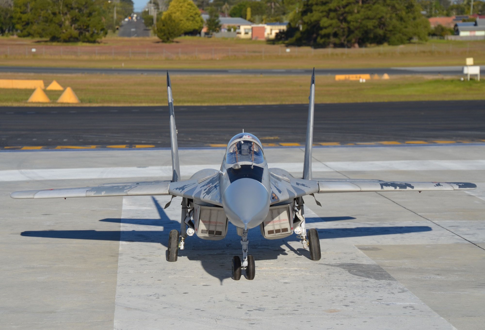
. If you have a look at the attached pic you can see the angle on mine. I think Craig managed to get his straighter than mine but i tried so many ways. It works fine though. Also my wheels are great but the wheel brakes are not that effective. My nose gear just clears the fuse on the way in. From memory i might have added some washers to the top bolts to change the angle slightly. I'll take some pics of my airbrake setup if you like.
. If you have a look at the attached pic you can see the angle on mine. I think Craig managed to get his straighter than mine but i tried so many ways. It works fine though. Also my wheels are great but the wheel brakes are not that effective. My nose gear just clears the fuse on the way in. From memory i might have added some washers to the top bolts to change the angle slightly. I'll take some pics of my airbrake setup if you like.
01-06-2019, 07:01 AM
#541

Guys there is some adjustment available that affects the stage at which the lower part of the nose strut folds during the retraction cycle. If you find it the wheels are hitting the fuse, disassemble the nose leg and slightly shorten the link on the inside of the nose leg. This will make the lower part of the nose leg folder more and earlier in the retraction cycle, thus tucking the wheels more before they hit the fuse. With that said, I also lengthened my nose doors to give more clearance.
01-07-2019, 05:52 PM
#543
My Feedback: (44)

Join Date: Sep 2004
Location: Wilmette,
IL
Posts: 439
Likes: 0
Received 0 Likes
on
0 Posts
Not too happy my new cylinder support brock broke off, it was made from plywood which now I need to incorporate them with aluminum and support them with couple ribs of plywood to distribute the force and another issue one of my power cables on one battery does not have a good connection , I bought those from a company they are conversions from Dean�s two multiplex connectors and a few other little issues that I need to attend to.
but no worries I should have all of these done before flying season .
but no worries I should have all of these done before flying season .
01-07-2019, 08:11 PM
#544
Looking good!
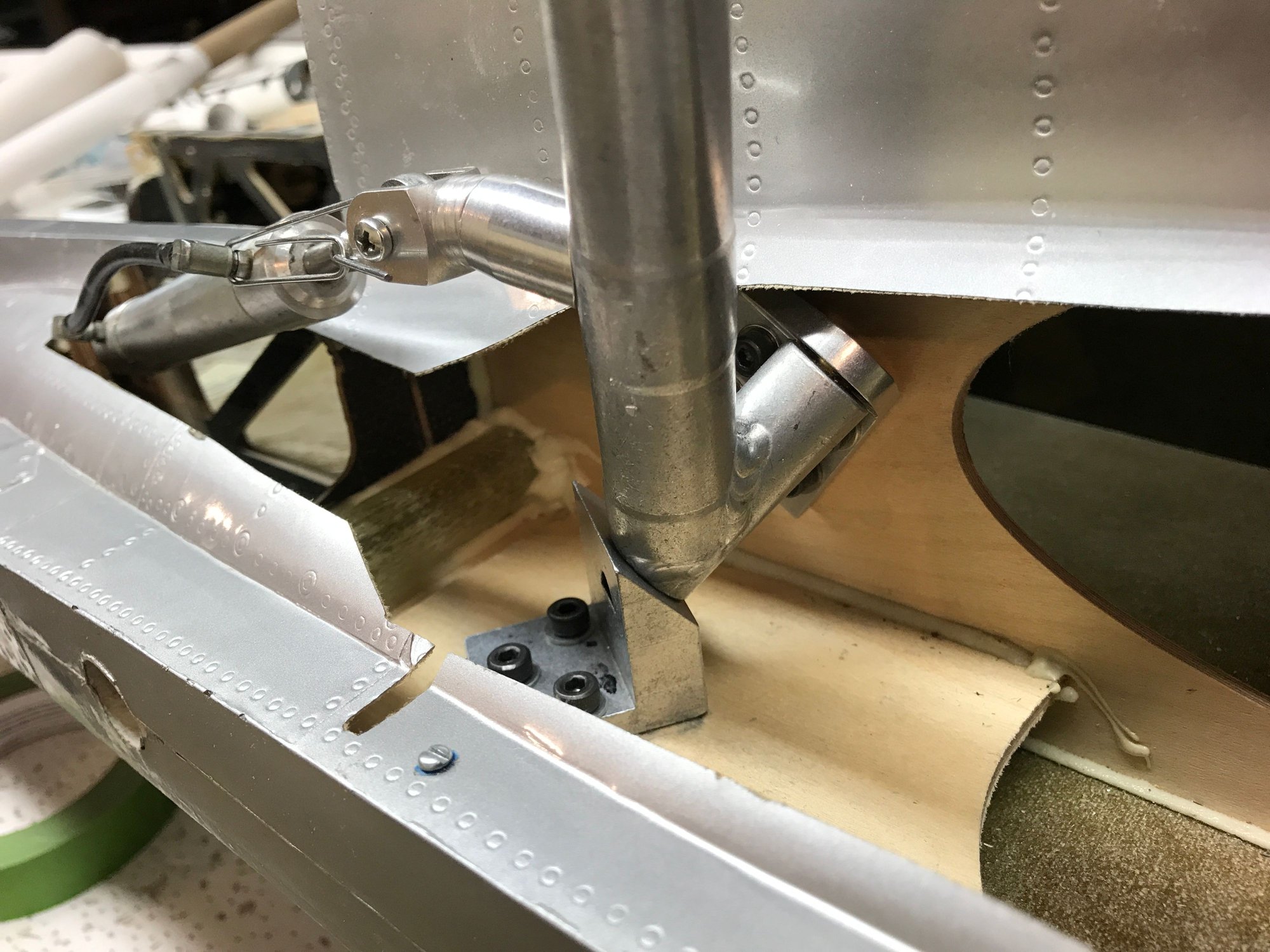
Request for the group, does anyone have some up close pictures of their main gear mounts? I know every install ends up being a bit different in these complex rotating gear airplanes, but I�d like to see the variable shim angles others have had to use. I�m working with a bed of about 1/4� of epoxy and thinking I want to grind it out to the bare wood rails and start over, just would like to see others first for good measure.
Request for the group, does anyone have some up close pictures of their main gear mounts? I know every install ends up being a bit different in these complex rotating gear airplanes, but I�d like to see the variable shim angles others have had to use. I�m working with a bed of about 1/4� of epoxy and thinking I want to grind it out to the bare wood rails and start over, just would like to see others first for good measure.
01-07-2019, 09:59 PM
#547
Thanks Jeremy. That also goes to show me just how different the mounts are from the hydraulic gear to the Matrix. Here you can see the epoxy bed. It is thicker in the front to form an angled shim which tilts the gear back, perhaps the original builder thought the strut needed to be perpendicular to the ground and not tilted forward a bit. I�m leaning more towards digging the epoxy out to start fresh at the wood.
You can also see how much outward angle the struts have when viewed from the front which appears to be quite common with most of these builds, not sure I�ll be able to do much about that.

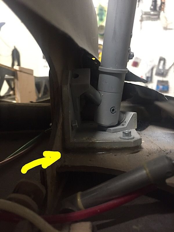
You can also see how much outward angle the struts have when viewed from the front which appears to be quite common with most of these builds, not sure I�ll be able to do much about that.
Last edited by Auburn02; 01-07-2019 at 10:01 PM.
01-08-2019, 04:55 AM
#548
Hello Auburn02, can you perhaps also make some pic from the inside of the fuse with the pneumatic cylinder and mounting?!
never seen that in any pic. Also Matrix has no pic of the installed gear.
Thanks, regards Martin
never seen that in any pic. Also Matrix has no pic of the installed gear.
Thanks, regards Martin
 01-08-2019, 06:05 AM
#550